
Test 8
IDEX / multi-tool alignment
One layer, two tools, a small station at every corner and edge of the bed. At each station T1 prints next to T0, and you read how far apart they landed, in X and in Y. The same gap everywhere is a plain offset; a gap that changes across the bed is mechanical.
More
- If the gap is the same everywhere, one number fixes it. If it changes across the bed, the cause is mechanical, and the pattern says where to look.
- There are two versions. Lite shows gap or overlap at a glance and uses under 0.5 g of filament. Vernier reads numbers to 0.05 mm and uses under 2 g. Both print in minutes.
- The interactive card turns your readings into the offset, a verdict for each mechanism and the lines to type into your firmware.
Open the file with File › Open project, never with Import. Set skirt loops to 0, and keep the tool offsets in one place only: in the firmware (RatOS) or in the slicer, never both (step 3).
What you need
To print
- An IDEX or multi-tool printer, in normal mode (not copy or mirror)
- The file for your bed size, Lite or Vernier
- PrusaSlicer 2.9 (2.7 is the minimum that opens the project), with your multi-extruder printer profile
- The same filament type in both tools, in two contrasting colours: the reference is PETG
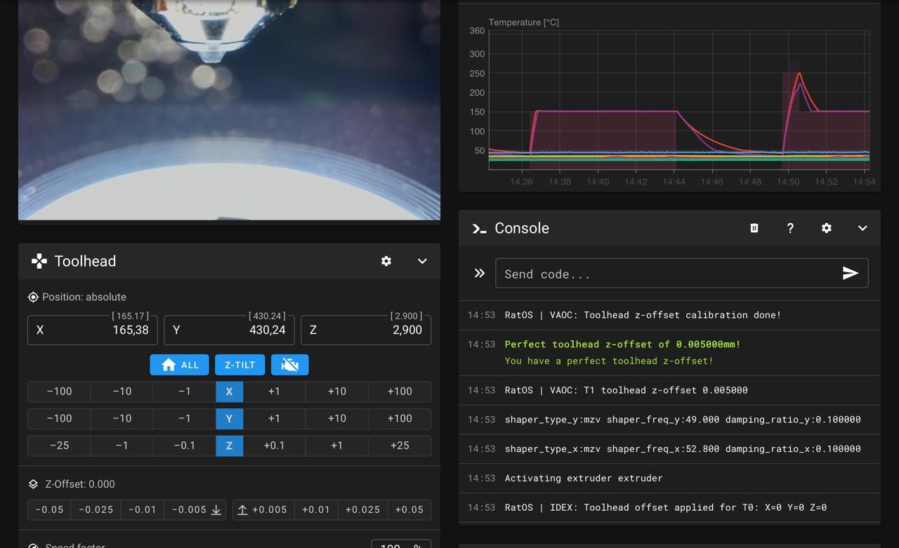
- A clean, levelled bed, with the Z offset between the tools already set
To read it
- A loupe (10×) or a phone camera with a macro mode
- A lamp you can move, for raking light
- The IDEX alignment card, on screen or printed
- Your current tool offsets (on RatOS:
idex_xoffsetandidex_yoffset)
Before printing
Step 1 What it is for: Lite or Vernier
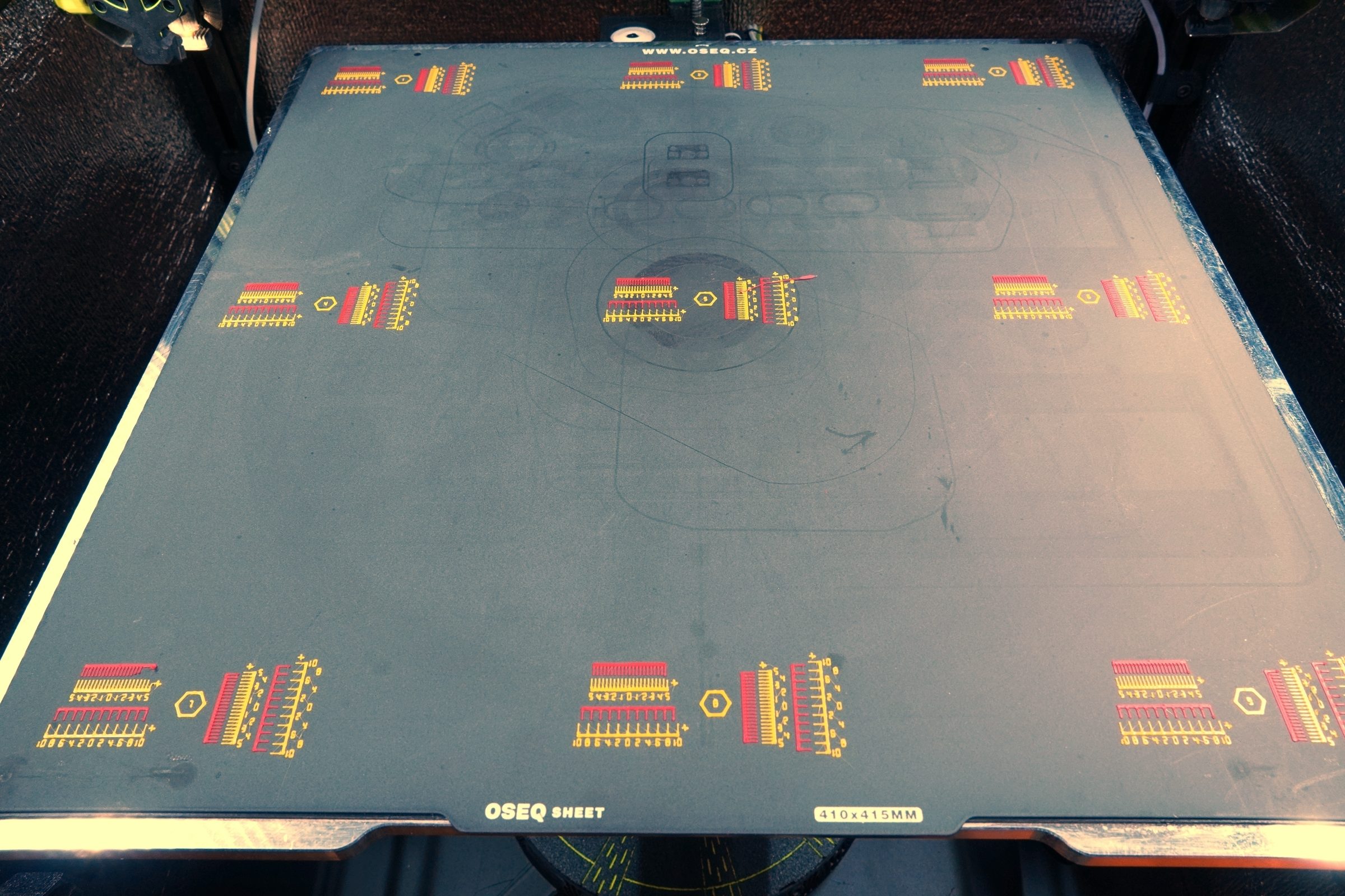
- It checks that T1 prints exactly where T0 does, everywhere on the bed.
- Lite: a quick check, gap or overlap, no numbers. Vernier: reads the offset to 0.05 mm.
- Use Lite after maintenance; use Vernier to set the offset, or after an automatic calibration.
More
- It checks that the second toolhead prints exactly where the first one does, everywhere on the bed. The difference is the tool offset. When it is wrong, a two-colour part shows a step where the colours meet, and a support material in the second tool lands next to the part instead of under it.
- BeginnerOn an IDEX printer the two toolheads are two separate carriages. The firmware stores how far apart their nozzles are, the offset, and shifts T1 by that amount. If the stored offset is wrong, every T1 line lands a little to the side. If the two carriages do not move the same way (belts, rails, a twisted gantry), the error even changes from one spot of the bed to another.
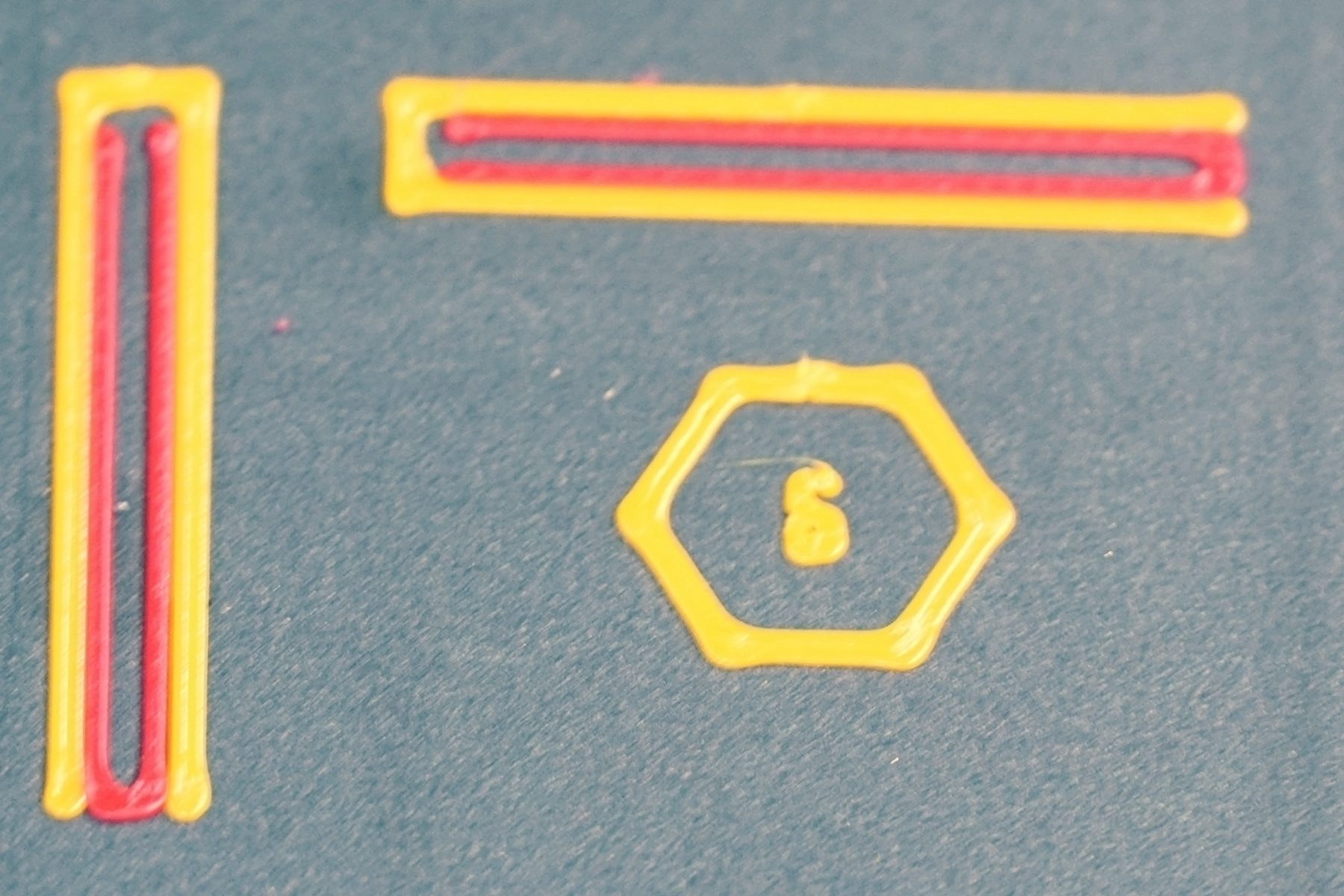
- Lite is the author's original nested-U test ("Calibrazione idex"), made parametric for HexCalibr. At each station, T0 prints an outer U and T1 an inner U that should just touch it. A gap on one side and an overlap on the other show which way T1 moved. One U reads X, the other reads Y, at every station. It answers "is it the same everywhere?" quickly, but gives no numbers.
- Vernier is new: at each station, an X scale and a Y scale like the vernier of a caliper. You read the offset directly, in 0.05 mm steps, from −1.0 to +1.0 mm. The card fits the readings of all stations and separates the offset from the mechanics.
- Use Lite for a quick check after maintenance, or to see whether the offset is the same over the bed. Use Vernier to set the offset, after an automatic calibration, or when Lite shows a difference between stations.
- RatOS VAOC and other automatic calibrations (the Prusa XL's pin, nozzle cameras) measure the offset at one place, without printing. This test checks the result in plastic, over the whole bed: it confirms that the stored offset is right where the parts are, and shows mechanical problems that a single spot cannot see, such as one carriage travelling farther than the other or a racked gantry.
- ExpertThe reading uses the centres of the ticks, not their edges, so line width, squish and flow do not change it. That is the advantage of the Vernier over the Lite and over checkerboard tests. The Lite reads edges: a line that is too wide or too thin shows as a gap or overlap on both sides.
Step 2 Download the right file
One file per test (Lite or Vernier) and per bed size.
| Preset | Files | Bed (mm) | Stations | Printers |
|---|---|---|---|---|
180 | idex-lite_ · idex-vernier_ | 180 × 180 | 5 | small beds |
250 | idex-lite_ · idex-vernier_ | 250 × 250 | 5 | 250 mm beds |
300 | idex-lite_ · idex-vernier_ | 300 × 300 | 9 | RatRig V-Core 4 300 IDEX, Sovol SV04, Tenlog TL-D3 |
350 | idex-lite_ · idex-vernier_ | 350 × 350 | 9 | 350 mm beds |
400 | idex-lite_ · idex-vernier_ | 400 × 400 | 9 | RatRig V-Core 4 400 IDEX |
500 | idex-lite_ · idex-vernier_ | 500 × 500 | 9 | RatRig V-Core 4 500 IDEX |
xl | idex-lite_xl.3mf · idex-vernier_xl.3mf | 360 × 360 | 9 | Prusa XL (any two tools) |
mk4 | idex-lite_mk4.3mf · idex-vernier_mk4.3mf | 250 × 210 | 5 | MK4/MK4S-size beds, multi-tool conversions only |
coreone | idex-lite_coreone.3mf · idex-vernier_coreone.3mf | 250 × 220 | 5 | Core One-size beds with more than one tool |
j1 | idex-lite_j1.3mf · idex-vernier_j1.3mf | 300 × 200 | 5 | Snapmaker J1 |
- Pick the preset for your bed size. If yours is not listed, take the next smaller one: the stations then sit a little further in, which is fine.
- Download the single .3mf file from the HexCalibr page on Printables (below), not a ZIP.
- Prusa XL: when the plate is empty, PrusaSlicer arranges a project on the XL automatically and may move the whole test up to 10 mm towards the front-left corner. That is fine: the test is one object, so the stations keep their places relative to each other, and the scale and skew results are not affected. Do not move single stations.
More
One file per test (Lite or Vernier) and per bed size. PrusaSlicer centres the test on your bed: the preset only decides how far out the stations go, about 10 mm from each edge.
- Beds of 300 mm and more get 9 stations (corners, edge midpoints and centre); smaller beds get 5 (corners and centre).
- Download the single .3mf file, not "Download all" as a ZIP: PrusaSlicer opens a ZIP's 3MF as plain geometry and the tool assignment is lost.
- Filament and time, PETG at a 0.2 mm first layer: Lite 0.17 g (5 stations) to 0.32 g (9 stations), a few minutes. Vernier 0.66 g to 1.19 g, about 3.5 to 17 minutes depending on your first-layer speed. A 0.3 mm first layer uses about 50 % more. These are our estimates; PrusaSlicer shows the real figures after slicing.
Step 3 Prepare the printer and the slicer
Tool offsets in one place only
The XY offset between the tools can live in the firmware or in the slicer. Use one, and set the other to zero. Corrected in both places, every change counts twice.
- RatOS keeps the offsets in the firmware (
idex_xoffset,idex_yoffset, set by VAOC or by hand). Then the slicer's Extruder offset must be 0, 0 for every extruder (Printer Settings › Extruder 2 › Position). - Other firmwares (Marlin
M218, the Prusa XL's nozzle offsets) also apply their offsets themselves. Use the slicer's Extruder offset only if your firmware does not. - Never "fix" a result by changing the slicer while the firmware also applies an offset.
- Load T0 and T1 with the same filament in two contrasting colours, both hot and primed.
- Set skirt loops to 0, turn off the wipe tower and ooze prevention, and print in normal IDEX mode.
- No skew correction for this test. A skew profile changes where the printer puts every point, and a wrong one distorts the results: it can look like a mechanical fault, or hide one. On Klipper,
SET_SKEW CLEAR=1turns it off (Klipper: skew correction). On RatOS a console command is not enough:START_PRINTand VAOC load the profile named byvariable_skew_profilein[gcode_macro RatOS]again (RatOS util.cfg). Comment that line out inprinter.cfgfor the test, and restore it afterwards.
More
- Two contrasting colours, same filament type: load T0 and T1 with, for example, orange and blue, or black and white. The reading depends on telling T0 from T1 at a glance. The reference photos are PETG; PLA works just as well.
- Both tools loaded, hot and primed. Use the temperatures you normally print with.
- Skirt loops = 0 (Print Settings › Skirt and brim › Loops (minimum)). The skirt would go around the whole layout: about 1.5 m of filament per loop on a 400 mm bed, sometimes one loop per tool.
- No wipe tower, no ooze prevention (Print Settings › Multiple Extruders). The test needs neither: there is only one tool change. No brim is already forced on the object.
- IDEX mode: normal (single toolhead, automatic tool change), not copy or mirror. RatOS does not apply
idex_xoffsetin copy or mirror mode. - A good first layer: bed mesh applied, and the Z offset between the tools already set (most multi-tool printers measure it automatically, for example RatOS with its Z probe and VAOC, the Prusa XL tool offset calibration, the Bambu Lab H2D nozzle offset calibration, the Snapmaker J1 Z offset calibration; otherwise set it by hand as your printer's manual describes). A T1 line that is squished or starved changes the line width: the Vernier does not care, but the Lite does.
- Elephant foot compensation is forced to 0 on the object, whatever your profile says. The whole test is one first layer: the compensation would shrink every line by its value (often 0.1–0.2 mm), eat the one-line ticks and shift every contact edge of the Lite. Do not set it back in the object's settings.
- BeginnerThe other settings forced on the object are there for the same reason, a clean single layer: Arachne perimeters (each tick becomes one bead), no supports, no raft, no ironing, no fuzzy skin.
Print it
Step 4 Open it as a project
Before you print: one object, two extruders
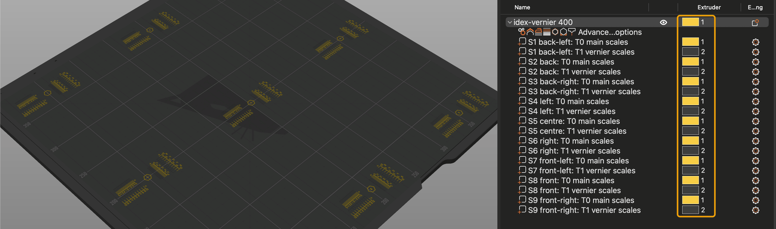
After opening, the object list on the right must show one object whose parts are named after the stations, assigned to extruder 1 and extruder 2.
- Every station has two parts, for example
S1 back-left: T0 main scales(extruder 1) andS1 back-left: T1 vernier scales(extruder 2). Lite:T0 outer UandT1 inner U. - Everything on extruder 1, or a pile of separate objects: do not print. Open the file again with File › Open project, not Import.
- Do not move, scale, rotate or arrange single parts. The card knows where each station sits relative to the bed centre.
- In PrusaSlicer, File › Open project (Ctrl+O, or ⌘O on macOS) and choose the .3mf.
- Choose your IDEX (multi-extruder) printer profile and a filament for each extruder.
- Opening the project replaces anything already on the plate. Print the test on its own.
More
- If you drag the file onto the window instead, PrusaSlicer asks what to do: choose Open as project. Import 3D models only drops the extruder assignment.
- The project carries no printer, filament or print profile: PrusaSlicer keeps yours. Choose your IDEX (multi-extruder) printer profile and a filament for each extruder.
- PrusaSlicer centres the test on your bed. The stations end up about 10 mm from the edges for the matching preset.
Step 5 Check the slice
One layer, one tool change
Slice and look at the Preview before printing.
- The vertical slider shows exactly one layer. Any first-layer height from 0.1 to 0.39 mm gives one layer.
- In the legend, switch the view to Tool: the T0 parts in one colour, the T1 parts in the other, at every station.
- The G-code has one tool change: all of T0 first, then all of T1. Export it and search for your tool-change command (for example
T1): one hit in the print, besides any in the start G-code. - No skirt around the layout. If there is one, set the loops to 0 (step 3).
- Click Slice now and switch to Preview.
- Zoom on a Vernier station: each tick must show as one single bead, with no tick missing. Lite: the outer and inner U are separate lines that touch.
- Check the object's settings (the gear icon next to the object in the list): elephant foot compensation 0.
More
- Pick your printer, print and filament profiles in the right-hand panel, as for any print.
- ExpertPrusaSlicer orders the tools of a layer to start with the last one used, so a single-layer print with two extruders gets one tool change. With
toolchange_ordering = optimizedthe order is T0 then T1.
Step 6 Print it
- Send it and start: a single layer, under 0.5 g for the Lite and under 2 g for the Vernier, done in minutes.
- Watch T1's first station: if its line is thin or missing, prime T1 and print again.
- Leave the print on the bed and read it there.
More
- Watch the first station of T1: if it starts with a thin or missing line, T1 was not primed. Prime it in your tool-change macro and print again.
- Leave the print on the bed. Read it there, before removing it. Peeling a single layer stretches it, and PETG on textured PEI hardly comes off flat.
- BeginnerWrite the date and the current tool offsets on a piece of paper next to the printer. You will compare the next test with this one.
Read it
Step 7 Find the stations
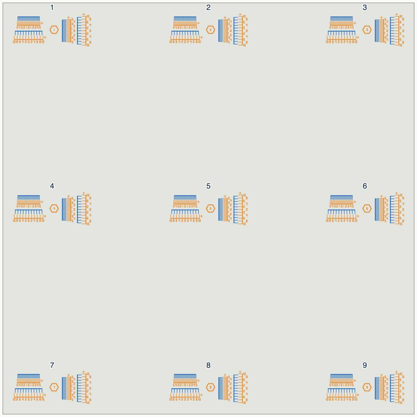
- Stations are numbered like a phone keypad seen from the front: 1 back-left, 5 centre, 9 front-right.
- Read on the bed, standing at the front, so left, right, front and back are the printer's. If you must turn your head, the badge tells you which way is up.
- Use a 10× loupe or a phone's macro mode, with raking light from one side.
More
- Stations are numbered like a phone keypad seen from the front of the printer: 1 back-left, 2 back, 3 back-right, 4 left, 5 centre, 6 right, 7 front-left, 8 front, 9 front-right. Beds under 300 mm have only 1, 3, 5, 7 and 9.
- Each station has a hexagonal badge with its number, printed by T0. The number reads upright when you stand at the front.
- BeginnerA 10× loupe or the macro mode of a phone makes the 0.05 mm steps easy. Use raking light: a lamp low and to the side, skimming across the lines, so each line casts a small shadow. Light from above makes them disappear into the plate.
- BeginnerRead one station at a time and write X and Y down at once, with the station number. Nine stations make 18 numbers: easy to mix up.
Step 8 Read the Lite: gap or overlap
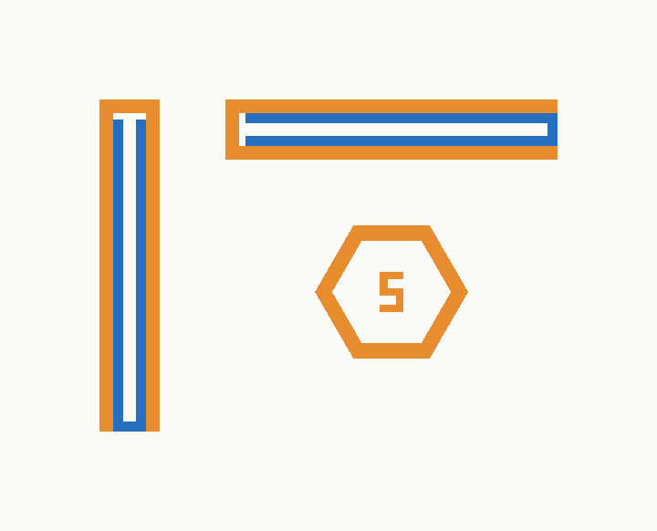
T0 prints the outer U, T1 the inner U. The vertical U reads X; the horizontal U reads Y.
| What you see | Meaning | On the card |
|---|---|---|
| Both contact lines look the same, no gap and no ridge | Aligned here (within about 0.1 mm) | 0 |
| Vertical U: gap on the left, overlap or ridge on the right | T1 sits to the right (+X) of T0 | X: + |
| Vertical U: gap on the right, overlap on the left | T1 sits to the left (−X) | X: − |
| Horizontal U: gap at the front, overlap at the back | T1 sits towards the back (+Y) | Y: + |
| Horizontal U: gap at the back, overlap at the front | T1 sits towards the front (−Y) | Y: − |
| Gap on both sides, or overlap on both | Not an offset: T1's line is thinner (or wider) than modelled | 0, and see the note below |
- Rule of thumb: T1 moved away from the gap, towards the overlap.
- Compare the stations. The same answer everywhere is a plain offset. An answer that changes from station to station is mechanics: print the Vernier and use the card.
More
Each Lite station has two nested U shapes. T0 prints the outer U, T1 the inner U, and T1's outer edges are modelled to touch T0's inner edges exactly. The vertical U (rails front to back) reads X; the horizontal U (rails left to right) reads Y.
- Common misreadingA gap on both sides is a width problem, not an offset: T1 under-extrudes, its first layer is too high, or the Z offset between the tools is off. An overlap on both sides is the opposite. Fix the first layer of T1 before trusting the Lite.
- ExpertOn the card, Lite readings count as ±0.1 mm. The fit then shows which mechanism changes the sign across the bed, but no offset to apply.
Step 9 Read the Vernier: the fine scale
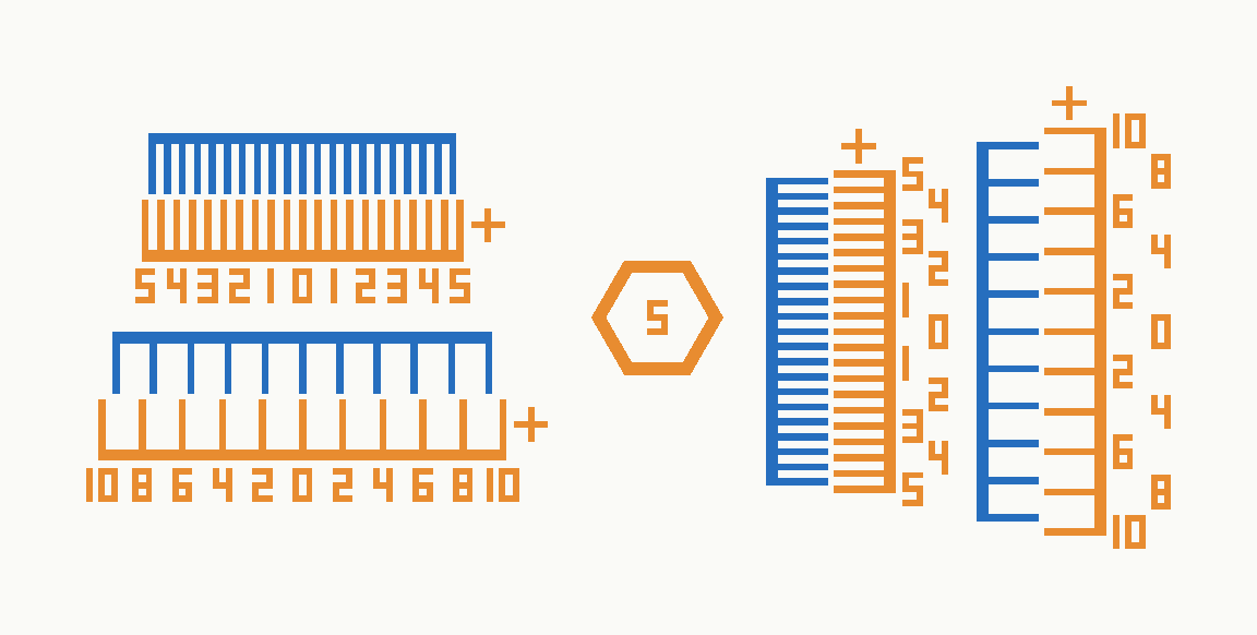
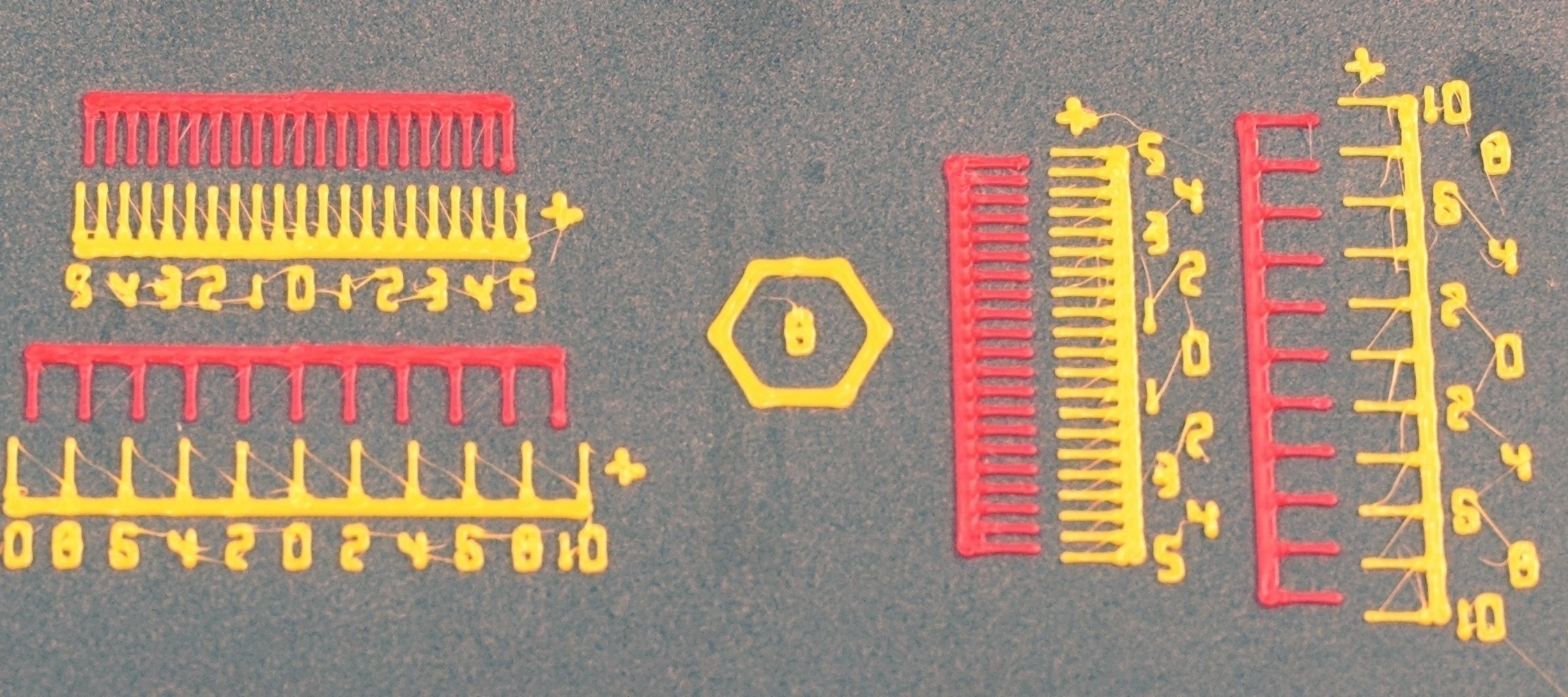
Each station has an X block on the left and a Y block on the right, each with a fine and a coarse scale.
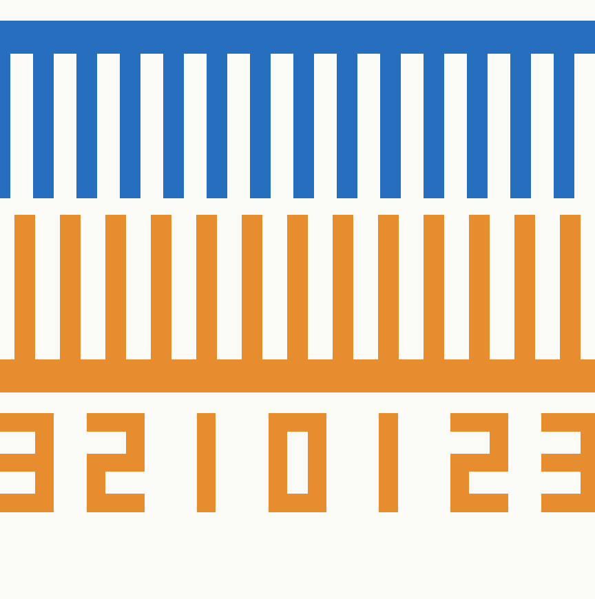
- Find the T1 tick that lines up best with the T0 tick next to it.
- Read the label next to it, in tenths of a millimetre ("1" = 0.10 mm); the unlabelled tick just beyond a label adds 0.05.
- Sign: positive on the "+" side, right in the X block and back in the Y block.
More
Each Vernier station has an X block on the left (ticks standing front to back, spread left to right) and a Y block on the right (ticks lying left to right, spread front to back), with the badge in between. Each block has a fine scale (labels up to 5) and a coarse scale (labels up to 10).
- T0 prints the main scale and its labels; T1 prints the vernier scale right next to it, with slightly closer ticks. In the X block the labels are below T0's comb; in the Y block, to its right.
- Find the T1 tick that lines up best with the T0 tick next to it, as if they were one straight line. Around it, the neighbouring ticks are off by the same amount in opposite directions, like an arrowhead pointing at the right tick.
- Read the number next to that T0 tick. The labels are in tenths of a millimetre: "1" = 0.10 mm, "3" = 0.30 mm. Only every second tick has a label: the unlabelled tick just beyond a label adds 0.05. One tick past the "2", away from 0, reads 0.25.
- The sign: a "+" marks the positive end of each scale, right in the X block and back in the Y block. A reading on the "+" side is positive, on the other side negative. Aligned on "0": reading 0.00.
- Example: in the X block the best tick is the first unlabelled one past "1", on the "+" side: X = +0.15. T1 prints 0.15 mm to the right of T0 there.
- Write X and Y for every station, for example
5: X +0.15, Y −0.05, and type them into the card. - ExpertIf two neighbouring ticks look equally good, the value is halfway between them (0.025 steps). That is optional and not yet verified at a 0.4 mm nozzle: the scale is rated at 0.05 mm.
- ExpertWhy it works: T0's fine ticks are 1.10 mm apart, T1's 1.05 mm. If T1 prints d mm to the right, its tick k sits at k × 1.05 + d and meets T0's tick k (at k × 1.10) when k = d ÷ 0.05. The label is the offset.
Step 10 When to use the coarse scale
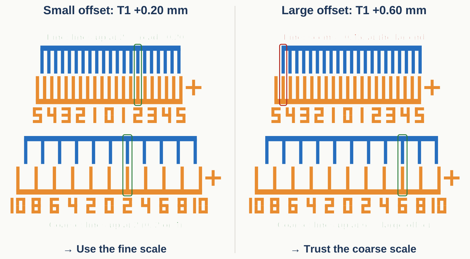
- Look at the coarse scale first. Find the T1 tick that continues a T0 tick. If it is 0, 2 or 4 (up to 0.4 mm), read the fine scale and leave the coarse box empty.
- If it is 6, 8 or 10, the offset is large. Either apply the coarse value, print again and read the fine scale, or type both readings into the card: it works out the true value.
More
- The fine scale covers ±0.50 mm, and it repeats: past 0.5 mm it seems to line up again near the other end. The coarse scale (0.2 mm steps, ±1.0 mm) tells you which window you are in.
- Also use it when the fine scale lines up nowhere, or only at its last tick ("5"): you are out of its range.
- ExpertOffsets above 1 mm are out of range of both scales. Correct roughly first (VAOC, or a single-spot test), then use this one.
Step 11 Common misreadings
- Find the "+" first, and judge a tick by the symmetry of its neighbours, not on its own.
- Print with skew correction off, and with a first layer that is not over-squished.
More
- Common misreadingA tick merged by squish: when the first layer is too low, neighbouring ticks spread and touch, and a blob looks like an alignment. Judge by the symmetry of the neighbours, not by one tick. If whole rows of ticks merge, raise T1's first layer (or the Z offset between the tools) and print again.
- Common misreadingElephant foot: a wide, squashed first layer makes every tick fatter and closes the gaps between them. The Vernier still reads the centres, but the alignment becomes hard to see. On the Lite, it closes the gaps on both sides. Check that the object's elephant foot compensation is 0 and the first layer is not over-squished.
- Common misreadingReading the wrong side: the labels carry no sign. Always find the "+" first: right in the X block, back in the Y block. Standing at the side of the printer, or looking at a photo turned around, flips the sign.
- Common misreadingMixing up the blocks: the X block is the one with ticks standing front to back. The Y block, right of the badge, has ticks lying left to right.
- Common misreadingReading the coarse scale as fine: the coarse labels go to 10 and step by 2 (2 = 0.20 mm); the fine labels go to 5 and step by 1.
- Common misreadingA skew profile was active: a wrong
[skew_correction]profile bends the results across the bed and sends you looking for a mechanical fault that is not there. One user lost most of a tuning session this way; with the skew set to 0 the readings made sense. Print this test with skew correction off (step 3), and measure the skew again only after the IDEX mechanics are fixed. - TipNot sure? Photograph the scale with the phone, zoom in, and count the ticks from "0" to the aligned one: each tick is 0.05 mm on the fine scale, 0.2 mm on the coarse.
Apply the result
Step 12 Enter the readings in the card
- Open the IDEX alignment card. Choose the bed preset of the file you printed and the test (Vernier or Lite), then type X and Y for each station. Fill the coarse boxes only when you read the coarse scale.
- Fix the mechanics before the offset. With a slope marked fix, no single offset is right everywhere. Correct the cause (next step), print again, then set the offset.
More
- The card fits a plane through the readings of each axis, reading = c0 + cx·x + cy·y, with x and y measured from the bed centre.
- It reports the offset at the bed centre (c0 for X and Y), and a verdict for each slope, judged by its effect at the outer stations: ok below 0.05 mm, watch from 0.05 to 0.10 mm, fix above 0.10 mm. It also shows rotation and shear, and flags any station more than 0.10 mm off the plane.
- With your current offsets typed in, it prints the exact RatOS
SAVE_VARIABLElines, plus the PrusaSlicer, Prusa XL and Marlin equivalents. - BeginnerYou can also print the card and write the numbers by hand: the rules are on page 1, the grid on page 2.
Step 13 What the pattern means
Each pattern points to one cause. "X reading" is the number from the X blocks, "Y reading" from the Y blocks.
| Pattern on the bed | Likely cause | What to do and check |
|---|---|---|
| Same reading everywhere (offset only) | A plain tool offset | Set the offset (next step). Nothing mechanical to check. |
| X reading grows from left to right | Carriage X scale: the two carriages travel different distances in X | Check both X belts (same tension, same belt), the pulley set screws and the motor mounts. If T0 measures right on a dimensional test, set T1's rotation_distance to old × (1 + slope). |
| Y reading changes from left to right | Rails not parallel, or gantry twist: T1's X travel is not parallel to T0's | Check that the X rail(s) are straight and bolted down along their whole length, and that the gantry is not twisted. A pure rotation can also be a loose toolhead mount. RatRig V-Core 4/4.1 IDEX: see the belt-length note below. |
| X reading changes from front to back | Racking or yaw of the gantry, seen differently by the two carriages | Square the gantry on both Y sides, compare the left and right Y belt tension, check the gantry joints. |
| Y reading changes from front to back | Rare: a Y scale difference, usually a misreading, a loose hotend or a moving bed | Re-read; check that both nozzles and hotends are tight and the bed does not move. RatRig V-Core 4/4.1 IDEX: the belt-length note below may apply too. |
| One station off (more than 0.1 mm from the others' plane) | A misreading, a bad first layer there (bed mesh), or local backlash | Re-read that station with a loupe; if it persists, check the bed mesh and the carriage at that spot. |
More
- Beginner"Y reading changes from left to right" means the T1 lines drift further from T0 the further you go across the bed: for example Y −0.10 at the left stations, 0.00 in the middle, +0.10 at the right. A fixed offset cannot fix that.
- TipRatRig V-Core 4/4.1 IDEX, belt length (field experience, the author's own printer): a Y gap between T0 and T1 that grew across the bed was fixed by shortening one toolhead's belt by 1–2 teeth, so that the two toolhead belts were the same length. Count the teeth, or compare the belt ends at the clamps of the two toolheads: a difference of 1–2 teeth is enough to cause it. Then re-tension both equally and print the Vernier again to confirm. RatRig's build guide asks for identical lengths for the two Y belts (V-Core 4.1 build guide, step 42; V-Core 4.0 IDEX Y belts); we found no official note on the toolhead belts. Treat it as a tip to check, not a rule.
- Rotation and shear (expert): the card also combines the two cross slopes. A rotation means T1's frame is turned against T0's (the toolhead or a carriage is mounted at a slight angle); a shear means the axes are not square to each other in the same way for both tools.
- ExpertThe slope is in mm per mm: an X slope of +0.0005 means T1 travels 0.05 % farther than T0, about +0.1 mm at 200 mm from the centre.
Step 14 Equalise the belts step by step
Belts suspected? Change one thing at a time and measure after each run.
- Move one belt anchor by one tooth, then re-tension both belts the same way.
- Redo the offset calibration (VAOC on RatOS), then print the test again.
- Compare with the previous run in the card: smaller is better; if it grew, go back one tooth.
More
When the Y reading changes across the bed (dy_dx, sometimes dy_dy) and the belts are the suspect, go one small change at a time and measure after each. Another RatRig V-Core 4 IDEX user reached about 0.05 mm this way, by moving only the belt anchoring at the toolheads, a little in or out each time.
| Run | Change made | Y left to right (dy_dx) | Y front to back (dy_dy) | Offset X / Y | Notes |
|---|---|---|---|---|---|
| 0 | none (starting point) | ||||
| 1 | |||||
| 2 | |||||
| 3 |
- Move one anchor by one tooth. Shift the belt end in one toolhead clamp by one tooth, in or out. Change one thing per run.
- Re-tension both belts the same way as before (same frequency or the same method you always use).
- Redo the offset calibration: VAOC on RatOS, or your printer's Z and XY offset routine. A belt change moves the nozzle, so the old offsets no longer hold.
- Print the test again. The Lite is enough to see whether you are going the right way; print the Vernier for the numbers once it looks close.
- Compare with the previous run: type the readings into the card, and compare the Y left to right and Y front to back effects with the run before. Smaller is better; if it grew, go back one tooth and try the other side.
- Keep a log like the table above, on paper or in the card (Remember this run keeps the previous result in your browser and shows it next to the new one; Copy results puts the text on the clipboard).
- BeginnerWrite down which clamp you moved and in which direction. After three or four runs nobody remembers.
Step 15 Set the offset
On every system: new value = old value + reading, X and Y separately, using the offset at the bed centre from the card.
- RatOS: type the two
SAVE_VARIABLElines the card writes (idex_xoffset,idex_yoffset) in the console. - PrusaSlicer, Prusa XL, Marlin: add the readings to the stored offset; the card writes the values.
- RatOS with
default_toolhead = 1: the roles of the two tools swap, and the rule becomes new = old − reading. This is derived from the RatOS macros and not tested on a printer: do the sign check below. - Print the Vernier again: the readings should now be within ±0.05 mm at every station.
More
Reading = where T1 prints minus where T0 prints, for the same commanded position. +X is to the right, +Y towards the back, seen from the front. On every system below: new value = old value + reading, X and Y separately, using the offset at the bed centre from the card.
- RatOS (Klipper IDEX,
default_toolhead = 0):idex_xoffset+= X andidex_yoffset+= Y. Type in the consoleSAVE_VARIABLE VARIABLE=idex_xoffset VALUE=<new>andSAVE_VARIABLE VARIABLE=idex_yoffset VALUE=<new>. The card writes both lines when you give it the current values, which are inratos-variables.cfg. Restart Klipper (FIRMWARE_RESTART) afterwards so that every macro reads the new values. - Example:
idex_xoffsetis 0.30 and the card says X +0.15: the new value is 0.45.idex_yoffsetis −0.12 and Y reads −0.05: the new value is −0.17. - PrusaSlicer (only if the firmware does not apply offsets): Printer Settings › Extruder 2 › Position › Extruder offset: add the readings to X and Y. RatOS users keep this at 0, 0.
- Prusa XL: in the printer's toolhead settings, the nozzle offset of the tested tool: add the readings (0.01 mm steps, ±1 mm). Re-running the automatic calibration overwrites manual changes.
- Marlin (
M218):M218 T1 X<old + X> Y<old + Y>, thenM500to store it. On dual X carriage machinesM218 T1 Xis the X2 home position: the same rule applies. - ExpertWhy "+": on RatOS the non-default toolhead runs with
SET_GCODE_OFFSET X_ADJUST={-idex_xoffset}, so a largeridex_xoffsetmoves T1 towards −X. PrusaSlicer subtractsextruder_offsetfrom the G-code coordinates, Marlin and the XL subtract the hotend offset from the commanded position. All three move T1 the opposite way of the offset, so adding the reading cancels it.
Step 16 Check the sign once (required with RatOS)
Required the first time you use the test with RatOS
The sign rule comes from the firmware source code. A deliberate change of 0.20 mm proves it on your machine in two short prints. Recommended on any other firmware too.
- Read station 5, X (call it a), add +0.20 to
idex_xoffset, and print the Vernier again. - It must now read a − 0.20. If it reads a + 0.20, the sign is reversed: use new = old − reading, and please tell us.
- Then set
idex_xoffsetto the value the card suggests.
More
- Print the Vernier and read station 5, X: call it a (for example +0.15).
- Add +0.20 to
idex_xoffset:SAVE_VARIABLE VARIABLE=idex_xoffset VALUE=<current + 0.20>. - Print the Vernier again and read station 5, X. It must now read a − 0.20 (in the example, −0.05): the reading decreases by 0.20.
- If it reads a + 0.20 instead, the sign is reversed on your machine: use new = old − reading, and please tell us (with your RatOS version and
default_toolhead).
Step 17 When to run it again
- After VAOC or any automatic offset calibration, to confirm it over the whole bed.
- After changing a nozzle, a hotend or a toolhead, or taking a toolhead off its carriage.
- After work on belts, pulleys, rails or the gantry, or after a crash.
More
- When two-colour parts show a step where the colours meet, or supports in the second tool land beside the part.
- A quick Lite every few months shows whether anything moved; the Vernier when it did.
Troubleshooting
Step 19 The slice or the print looks wrong
- Everything prints with one tool, or the stations are separate objects: the file was imported, or came from a ZIP. Open the single .3mf with File › Open project.
- A skirt circles the whole bed: set Print Settings › Skirt and brim › Loops (minimum) to 0.
- Two layers instead of one: the first-layer height is 0.4 mm or more. Use 0.1 to 0.39 mm for this print.
More
- A wipe tower appears: turn it off in Print Settings › Multiple Extruders. The test does not need it.
- Stations too close to the edge, or off the bed: the preset is for a bigger bed. Use the one for your bed size, or a smaller one.
- Ticks missing or merged in the Preview: check the object's settings (elephant foot compensation 0, Arachne) and that the object was not scaled.
- T1's first station is thin or missing: T1 was not primed after the tool change. Prime it in the tool-change macro and print again.
Step 20 The readings make no sense
- The fine scale lines up nowhere, or at its last tick: the offset is beyond ±0.5 mm. Read the coarse scale.
- The reading changes across the bed: that is mechanics, not offset. See what the pattern means.
- After applying the correction the error doubled: the sign is reversed on your setup (or the offset is set in both the firmware and the slicer). Do the sign check and set the slicer's extruder offset to 0 on RatOS.
More
- The card says coarse and fine disagree: one of the two is misread. Re-read both, starting from the "+" end.
- Gap or overlap on both sides of the Lite: a line width problem, not an offset. Check T1's flow and first-layer height.
- The Y gap grows across the bed on a RatRig V-Core 4/4.1 IDEX: check that the two toolhead belts are the same length. Count the teeth, or compare the belt ends at the clamps; 1–2 teeth of difference are enough. Re-tension both equally and print the Vernier again (field experience, the author's own printer).
- The readings change across the bed in a way no belt or rail explains, or change after a restart: check that no skew correction was active (step 3). On RatOS look for
variable_skew_profilein[gcode_macro RatOS]:START_PRINTloads it even after aSET_SKEW CLEAR=1in the console. - Nothing changes after
SAVE_VARIABLE: the printer is in copy or mirror mode, where RatOS does not applyidex_xoffset, or the value is not reloaded yet. Print in normal mode. - One station far off the others: re-read it with a loupe; then check the bed mesh and the first layer at that spot.